Elcon PFC-2500
The Elcon PFC-2500 is used to charge the internal battery pack of our electric vehicles.
Operation
Plug the charger into a 120v 20A circuit. Attach the battery connector to the vehicle. Finally, attach the BMS communication cable. The BMS cable should be attached last to ensure that all other connections are solid before sending a charge payload to the charger.
Warning
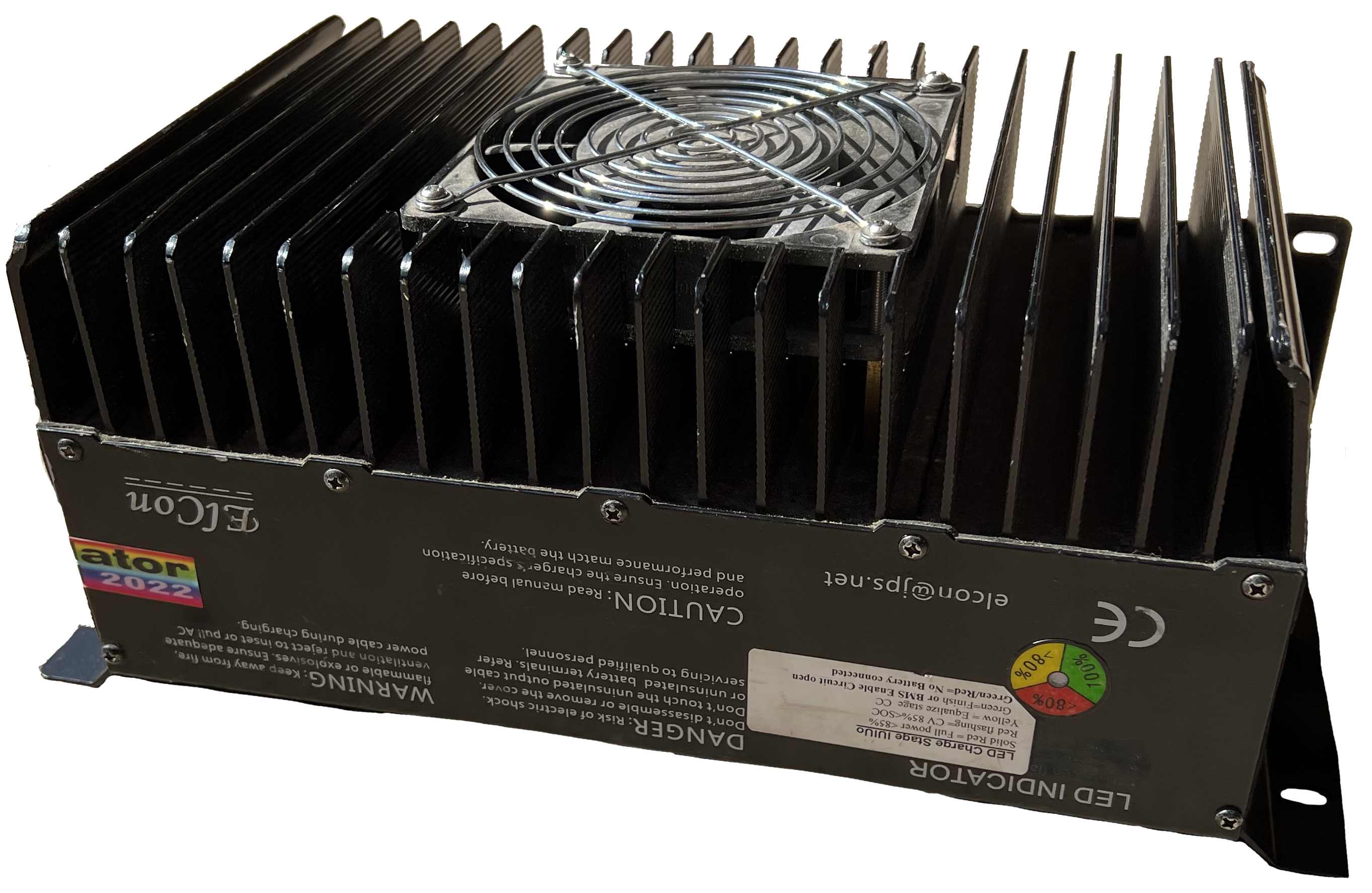
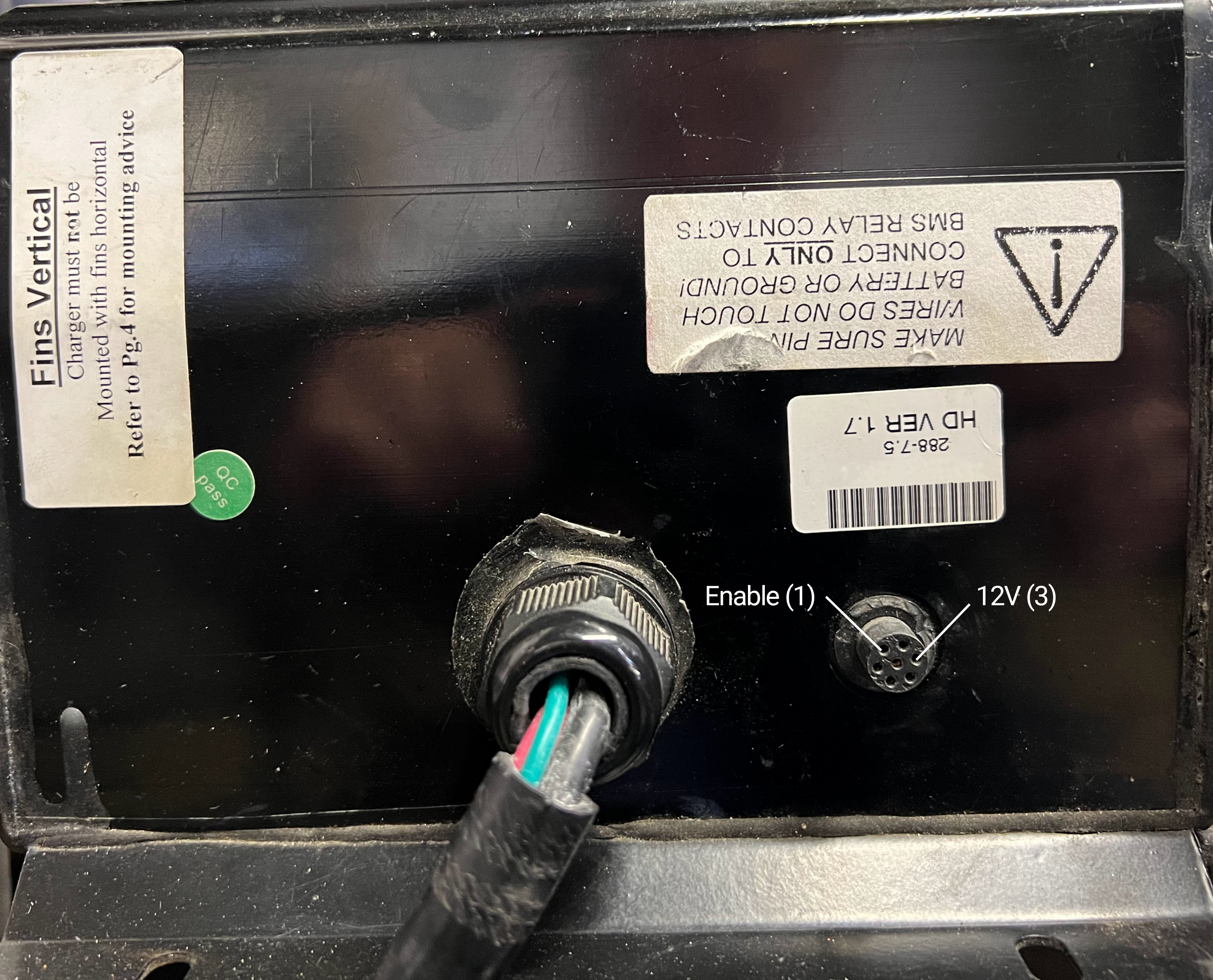
The PFC-2500 must be mounted in a valid orientation to ensure proper operation while charging. The best orientation is when the cooling fins are vertical with open space above and below them. Mounting the charger on a metal wall or frame will provide additional conductive cooling and also ground the frame.
LED Charge State
The charger state led is located on the longer side of the Elcon PFC-2500 surrounded by a red, yellow, and green label. The state of the led is represented by the following statuses:
| LED State | Description |
|---|---|
| Solid Red | Full Power < 85% |
| Flashing Red | CV 85% < SOC |
| Solid Yellow | Equalize stage CC |
| Solid Green | Finished or BMS Enable Circuit Open |
| Alt Green / Red | No Battery Connected |
Pinouts
The charger can be configured to communicate with the BMS over relay or CAN bus control. Our charger is configured to use relay control which will activate the charger if the trigger circuit is closed. In order to trigger the charger, Pin 1 (Enable) must be connected to Pin 3 (12V). The use of a relay connected to the BMS is advised to ensure proper operation of the charger.
Warning
The charger will not output power (solid green led) unless the BMS circuit is closed.
Supported Batteries
The Elcon PFC-2500 supports Flooded, Gel and Advanced Glass Mat (AGM) lead acid, and Lithium Iron Phosphate (LiFePO4). The charger is programmed at configuration time, so the desired configuration will vary from customer to customer.