Timer Input Capture
When to Use
Timer Input Capture should be used when we want to count an incoming frequency or PWM signal from Hall Effect Sensors and other PWM sources.
Description
Timer Input Capture is a feature on the STM32 that allows us to save the exact time that a PWM signal has a rising edge in a reliable fashion. A timer is configured and each time a rising, falling, or both edges are detected, the current value in the timer is stored into a buffer. Optionally (and most often), a callback is fired on each of these captures which gives the code a convenient place to calculate the difference between the current and last capture to determine the frequency.
Case Study: Wheel Hall Effect Sensor
In this example, we will look at how to implement a single output wheel hall effect sensor with an STM32. We want to be able to get the frequency of this sensor at any time which can then be used to compute RPM/ground speed.
Note
This guide was created for the STM32F446RE. This feature is available on all STM32s but some features may appear different then what is shown below.
Configure Timer in STM32CubeMX
We first need to find a suitable timer to use as our input. These typically come in 16-bit and 32-bit varities. It is often preferred to use a 32-bit timer to prevent overflows, but we will use a 16-bit timer in this example.
In this example, we will be using TIM1, CH3. Firstly, we need to select that channel, and then select Input Capture direct mode.
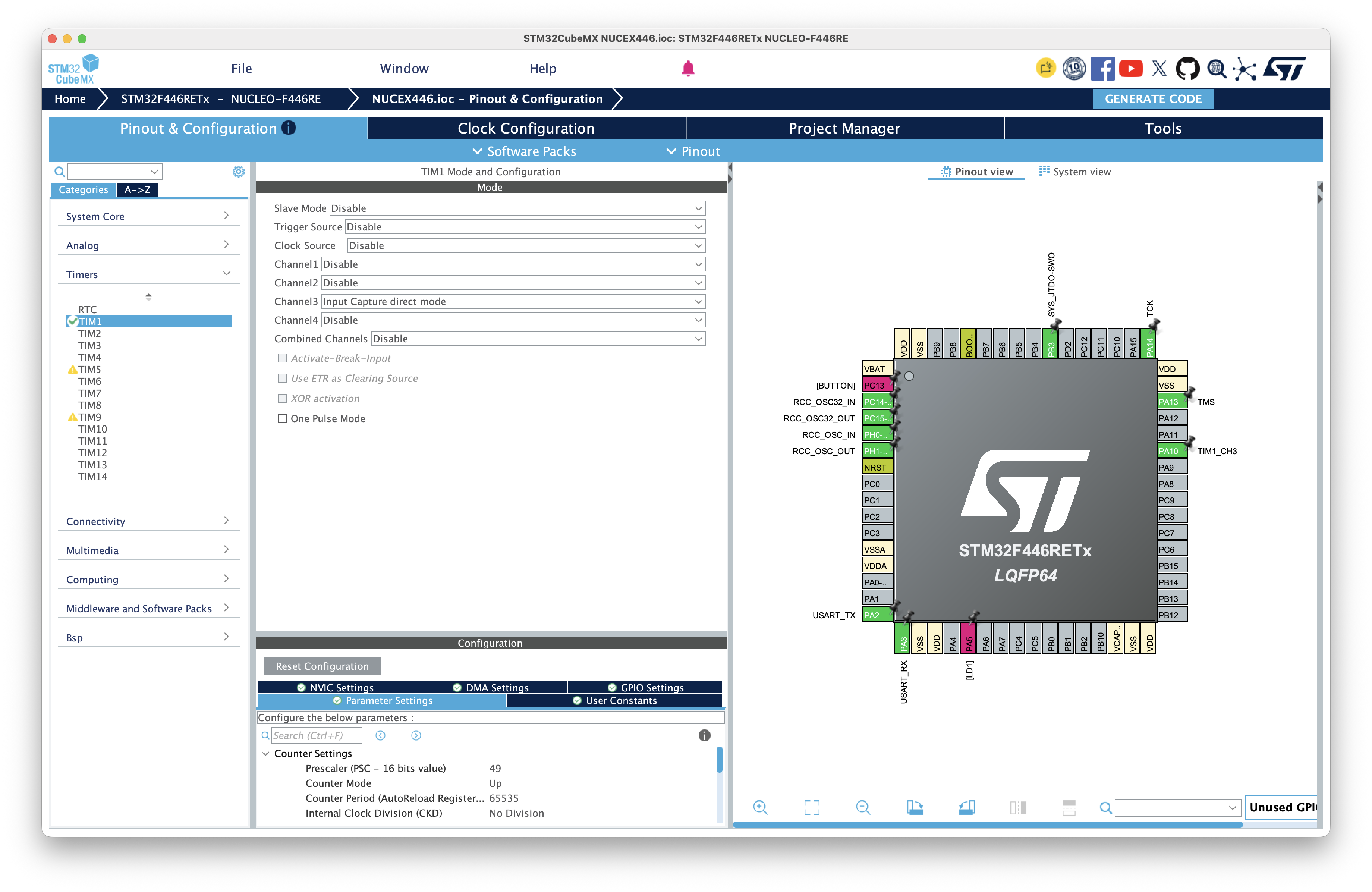
Next, we need to determine the Prescaler (PSC) value of the timer. This will be used to reduce the speed of the timer to better match the resolution and timing we want for the hall effect. We need to determine the clock speed for the selected timer (TIM1 in this case).
On our STM32, the APB1 speed for TIM1 is listed as 50Mhz.
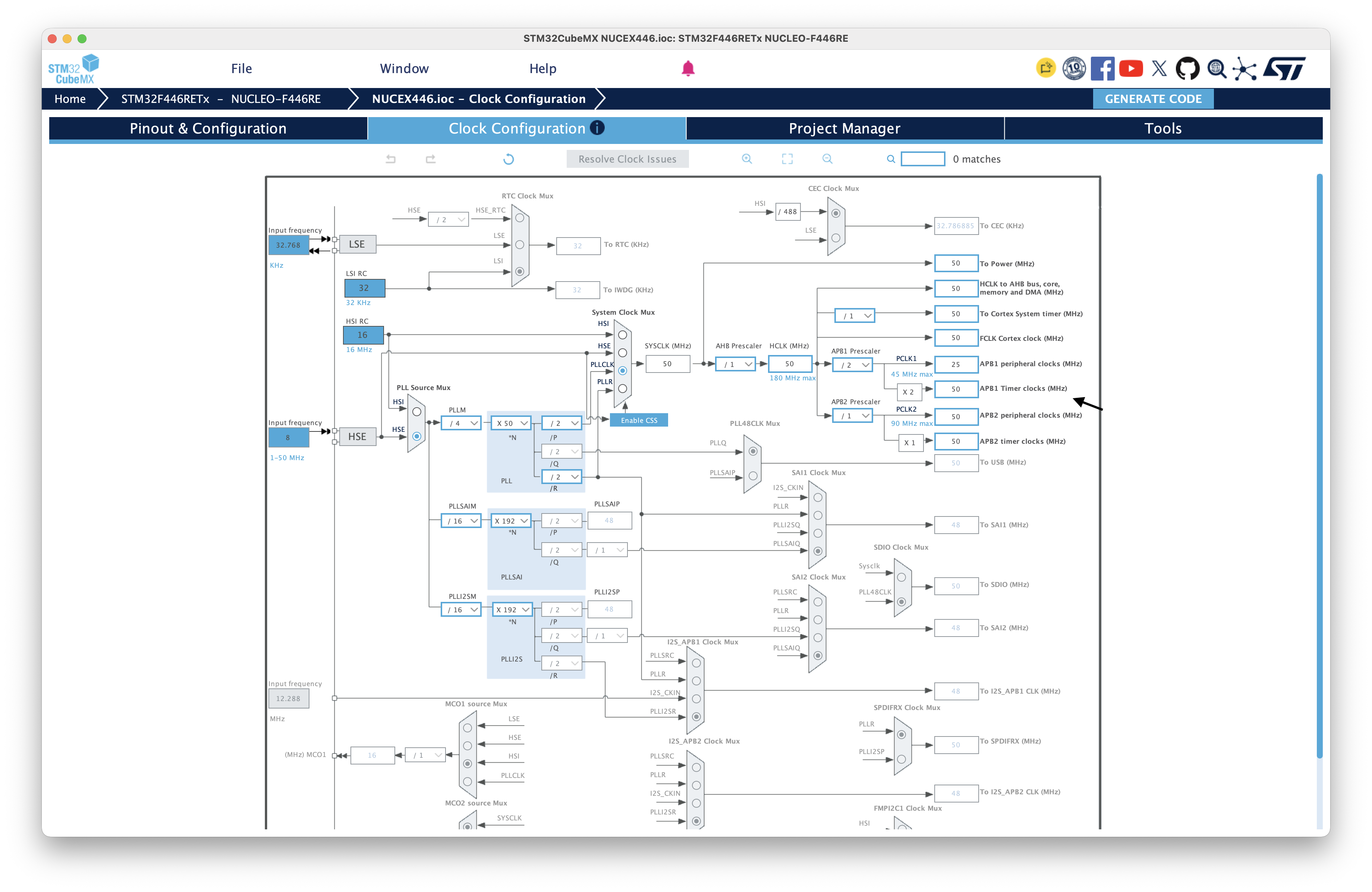
We now need to determine the Prescaler (PSC) value. This is the most important part of this process. The timer prescaler should be chosen so that the timer has enough resolution to measure the fastest expected pulse value, while still allowing for a long enough period of time before the timer overflows. As a general rule, we target a 1 MHz counter. At this frequency, each timer tick represents exactly 1 µs, making the timer values easy to reason about and the resulting calculations straightforward.
In order to find PSC, we use the following formula.
Assuming we want to set our timer to 1 MHz, we will use the following to find PSC.
Therefore, the timer prescaler should be configured to 49, resulting in a timer counter frequency of 1 MHz, or one timer count every microsecond.
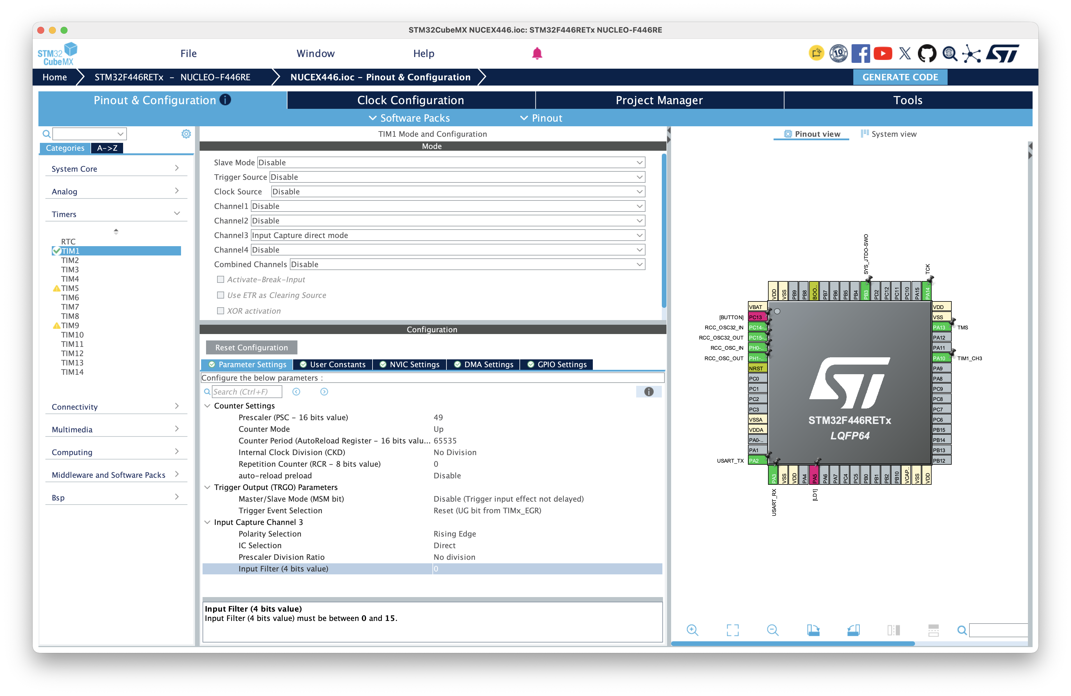
We now need to make sure all of the settings are correct for the selected timer.
Timer Settings
| Setting | Value | Description |
|---|---|---|
| Prescaler (PSC) | 49 |
Divides the 50 MHz timer clock to produce a 1 MHz counter (1 µs per tick). |
| Counter Mode | Up |
Timer counts upward from 0 to ARR. |
| Counter Period (ARR) | 65535 |
Maximum value for a 16-bit timer. |
| Internal Clock Division (CKD) | No Division |
Uses the timer clock directly without additional division. |
| Repetition Counter (RCR) | 0 |
Not used for input capture. |
| Auto-Reload Preload | Disable |
New ARR values take effect immediately. |
Trigger Output (TRGO)
| Setting | Value | Description |
|---|---|---|
| Master/Slave Mode (MSM) | Disable |
Timer operates independently. |
| Trigger Event Selection (TRGO) | Reset (UG bit from TIMx_EGR) |
Default setting. Not used for basic input capture. |
Input Capture Settings
| Setting | Value | Description |
|---|---|---|
| Polarity Selection | Rising Edge |
Capture the timer value on each rising edge of the Hall effect signal. |
| IC Selection | Direct |
Capture directly from the selected timer input (TI3). |
| Prescaler Division Ratio | No Division |
Capture every valid edge. |
| Input Filter | 0 |
No digital filtering. Increase only if the Hall signal is noisy or bouncing. |
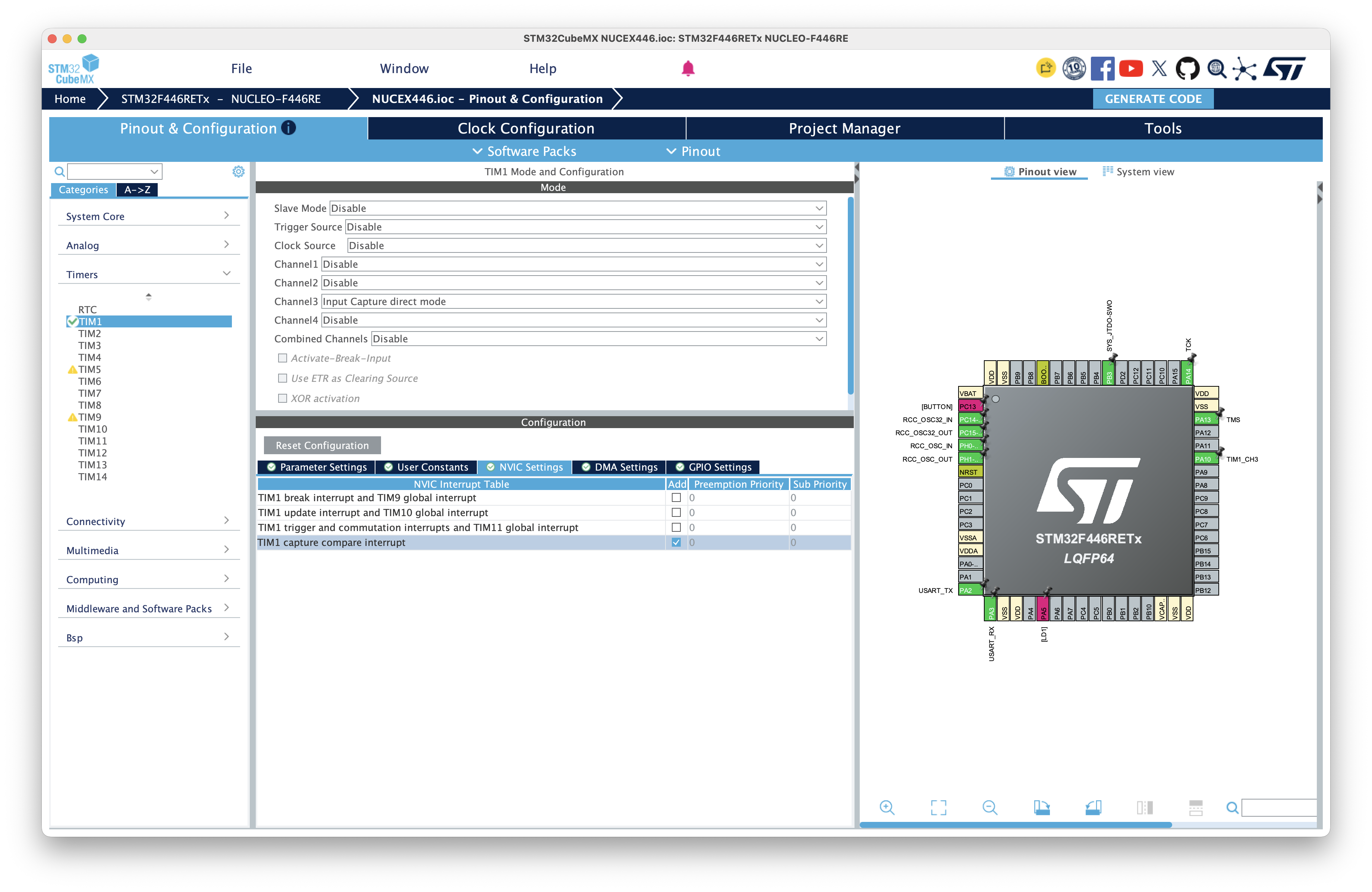
Finally, we need to enable an interrupt to handle the capture event. Select the NVIC Settings tab under the current timer, and enable TIMx capture compare interrupt.
We are now ready to implement this solution in code!
Implement Calculations in Code
Let's create some variables to store our capture data.
static volatile uint16_t last_capture = 0;
static volatile uint32_t period_ticks = 0;
static volatile bool first_capture = true;

volatile uint32_t capture_count;
Next, we need to initialize the interrupt callback. We will do this immedietly after MX_TIM1_Init();
int main(void)
{
    MX_TIM1_Init();
    /* USER CODE BEGIN 2 */
    HAL_TIM_IC_Start_IT(&htim1, TIM_CHANNEL_3);
    /* USER CODE END 2 */
}
We next need to add a capture callback function with the following name. The HAL library will automatically find the function and call it when a new rising edge is detected.
void HAL_TIM_IC_CaptureCallback(TIM_HandleTypeDef *htim)
{
    // In this case, we only want to handle events on TIM1 CH3. You can support additional logic here for more inputs.
    if (htim->Instance != TIM1 ||
        htim->Channel != HAL_TIM_ACTIVE_CHANNEL_3)
    {
        return;
    }

    // Read last capture
    uint16_t capture =
        (uint16_t)HAL_TIM_ReadCapturedValue(htim, TIM_CHANNEL_3);

    // Don't calculate period ticks if first capture, but save it.
    if (first_capture)
    {
        last_capture = capture;
        first_capture = false;
        return;
    }

    // Calculate period ticks.
    period_ticks = (uint16_t)(capture - last_capture);
    last_capture = capture;
}
Finally, we will handle read this value and print it out.
while (1)
{
    if (period_ticks != 0)
    {
        uint32_t frequency = 1000000UL / period_ticks;

        printf("Frequency: %lu Hz\r\n", frequency);
    }

    HAL_Delay(100);
}
Limitations
This implementation will correctly handle a single timer overflow event, since the period_ticks calculation uses unsigned arithmetic, which automatically wraps around the 16-bit timer range.
Warning
This approach only works if at most one timer overflow occurs between consecutive capture events. For lower pulse frequencies where multiple overflows may occur, an overflow counter or timeout mechanism is required.
In an ideal setup, some sort of timeout would be implemented anyways which would just set the value to zero if no capture has been detected in a certain amount of time. This is what vehicles do in practice and should be implemented here.